The CD101/CD901 controller family is an older, discontinued style. This page keeps the manual notes for existing installations, while the current DTXG-S controller is the product to review first for new kiln, oven and furnace replacement work.
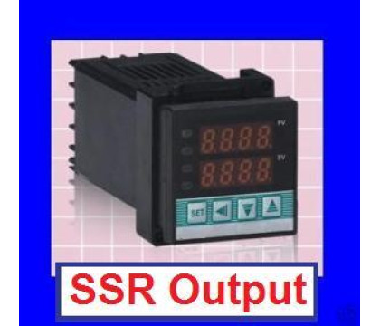
The DTXG-S gives you a current 1/16 DIN PID controller with SSR output, universal input for common thermocouples and RTD sensors, Fahrenheit/Celsius display, PID or ON/OFF control, auto-tuning and alarm functions. For most new builds, that is the practical upgrade path from the older CD101/CD901 style controller.
ModelDTXG-S
Price29.50 USD
This is a similar replacement, not a guaranteed pin-for-pin replacement. Verify input type, supply voltage, SSR output, load wiring and controller ratings before installing.
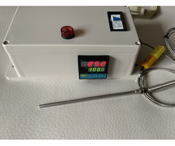
Want the PID controller already built into a plug and play box?
These plug-and-play controller boxes include the PID controller used above, plus the enclosure, breaker and sensor package shown on each product page.
A ready-to-go upgrade for shoppers using the CD101 manual to rebuild a controller. It packages the PID controller inside a plug and play box with a circuit breaker, SSR, alarm light/buzzer and 6 in K-type probe, reducing the loose wiring work needed for a basic panel controller.
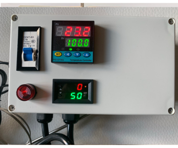
Choose this version when the older controller was part of a timed kiln or oven process. It adds the T1/T2 timer to the plug and play PID box, with breaker, SSR, enclosure and 6 in K-type probe already packaged together for a cleaner replacement path.
ModelDTX-P&P-DT
Price173.00 USD
What This Manual Covers
Controller Models
CD101, CD401, CD501, CD701, CD901 and related panel PID temperature controllers.
Kilns, ovens, furnaces, heat treating equipment and other systems that need controlled heater output.
Specification
Original Manual Value
Why It Matters
Input support
Thermocouple, RTD, standard current and voltage signals
Match the controller input code to the sensor or process signal before running the load.
Measurement accuracy
+/- 0.5% FS; cold junction compensation +/- 2°C
Use a separate reference thermometer if the process requires tighter calibration.
Display range
PV/SV display: -1999 to +9999
The usable range still depends on the selected input code and limiter settings.
Control modes
PID, ON/OFF when P is 0, auto setting / auto-tuning
Most heater applications should use PID after the controller has been tuned.
Environment
0-50°C, 0-85% RH, no corrosive gas
Keep the controller in a clean panel/enclosure away from heat, moisture and vibration.
Quick Start
1
Wire First, Power Last
Finish all power, input, sensor, output and alarm wiring before energizing the controller. Do not use the controller in flammable or explosive gas environments.
2
Confirm Input Type
At startup the controller briefly shows the selected input type and range before returning to the PV/SV display. If the sensor type is wrong, correct the input code before controlling a heater.
3
Set SV Temperature
From the normal PV/SV display, press SET until SV flashes. Use the shift key to choose the digit, then use the up/down keys to set the required temperature. Press SET again to return.
4
Run Auto-Tune
After the input, output and set value are correct, hold SET for parameter mode and set AT to 1. The controller calculates PID values and returns AT to 0 when tuning ends or is suspended.
5
Lock Settings
Use LCK after setup to prevent accidental changes. Lock levels still let locked values be monitored on the display.
6
Watch Fault Messages
If the display shows an input fault, power down and check sensor wiring, polarity and the selected input range before continuing.
Panel, Display And Keys
Label
Manual Meaning
Use On This Controller
PV
Measurement value / mode display value
Shows the process temperature or the parameter symbol during setup.
SV
Setting value / mode display value
Shows the target temperature or the selected parameter value.
AT
PID auto calculation indicator lamp
Indicates auto-tuning activity.
OUT1 / OUT2
Output indicator lamps
Show when the control outputs are active.
ALM1 / ALM2
Alarm indicator lamps
Show alarm output status when alarm functions are configured.
SET
Setting mode key
Press to enter SV setting; hold for parameter setting; press again to save/cycle.
Shift / R/S
Shift key
Moves the active digit while editing values. Used with SET to enter advanced configuration after unlocking.
Up / Down
Value keys
Increase or decrease the selected digit/value.
Common Parameter Reference
From the normal PV/SV display, hold SET for about three seconds to enter parameter setting mode. Press SET to cycle through the available symbols. The controller returns to the normal display after about 30 seconds without key operation.
Symbol
Manual Name
What It Changes
Setting Range
Typical Factory Value
ALM1 / ALM2
Alarm Set Value
Alarm thresholds for deviation, process or SV alarms.
-1999 to +9999°C or -199.9 to +999.9°C
50
AT
Auto-Tuning
Starts or cancels PID auto-tuning.
0: end/suspend; 1: start
0
ST
Self-Tuning
Turns self-tuning on or off where supported by the ordered model.
0: suspend; 1: start
0
P
Proportional Band
PID proportional action. Setting P to 0 changes control to ON/OFF action.
1 to span or 9999°C; 0 for ON/OFF
30
I
Integral Time
Integral action used to remove offset in proportional control.
1 to 3600 seconds; 0 disables integral action
240
D
Derivative Time
Derivative action used to reduce ripple and improve stability.
1 to 3600 seconds; 0 disables derivative action
60
Ar
Reference Value
Set automatically after auto-tuning; not normally set by hand.
0 to 100%
25
T
Heat-Side Proportional Cycle
Control output cycle time for the heating side.
1 to 100 seconds
20 seconds for relay; 2 seconds for voltage pulse / triac trigger
Pc
Cool-Side Proportional Band
Cool-side proportional band for heat/cool PID action.
1 to 1000% of heat-side proportional band
100
db
Dead-Band
Gap between heat-side and cool-side proportional bands.
-10 to +10°C or -10.0 to +10.0°C
0
t
Cool-Side Proportional Cycle
Control output cycle time for the cooling side.
1 to 100 seconds
20
Pb
PV Bias
Sensor correction added to measured PV.
-1999 to +9999°C or -199.9 to +999.9°C
0
LCK
Set Data Lock
Controls which SV, alarm and parameter values can be changed.
0000 to 0111 lock levels
0000
Set Data Lock Levels
LCK Value
What Can Be Changed
0000
SV and parameters can be set.
0001
Only SV and alarms ALM1 / ALM2 can be set.
0010
Only setting items other than ALM1 / ALM2 can be set.
0011
Only setting items other than SV can be set.
0100
Only SV can be set.
0101
Only ALM1 / ALM2 can be set.
0110
Only setting items other than SV and ALM1 / ALM2 can be set.
0111
SV and parameters cannot be set; values can only be monitored.
Advanced Configuration Mode
Use this mode only when the controller input type, alarm behavior, control direction or output behavior must be changed. In parameter mode, set LCK to 1000, press SET to confirm, then hold SET and Shift / R/S together for about three seconds until the PV display shows Cod.
Area
Original Manual Options
Use
Cod = 0000 input type
0000 K, 0001 J, 0010 L, 0011 E, 0100 N, 0101 T, 0110 U, 0111 R, 1000 S, 1001 B, 1010 W5Re/W26Re, 1011 P12, 1100 PT100, 1101 JPT100
Select the sensor family before choosing the range code.
Alarm type
000 no alarm, 001 upper-limit bias, 010 upper/lower-limit bias, 011 process high, 101 lower-limit bias, 110 alarm in area, 111 process low
Choose what condition drives ALM1 or ALM2.
Standby alarm
0 no standby alarm, 1 standby alarm enabled
Prevents selected alarm action until the process has first entered the non-alarm region.
Most heater/kiln/oven applications use reverse operation.
Main output type
0 time-scale output, 1 continuous output 4-20mA
Use time-scale output for relay, SSR pulse or triac-style control.
Alarm excitation
0 excitation alarming, 1 non-excitation alarming
Sets alarm relay behavior for ALM1 and ALM2.
Cod = 0001 limits
Upper limit, lower limit, decimal point 0-3, main output dead band, ALM1/ALM2 dead band, digital filtering 0-100
Use these to limit operator setpoints, set hysteresis/dead band and smooth noisy readings.
Model Code Notes
Code Area
Common Values In The Manual
Control action
F reverse PID/autocalculation, D forward PID/autocalculation, W heat/cool water cooling, A heat/cool air cooling.
OUT1
M relay contact, 8 DC 4-20mA current, V voltage pulse, G triac trigger, T triac.
OUT2
No symbol for F/D control, M relay contact, V voltage pulse, T triac.
Alarm codes
N none; A/B/C/D deviation or area alarms; E/F/G standby deviation alarms; H/J process high/low; K/L standby process high/low.
Communication
N no communication, 5 RS-485 two-wire system.
Fault Codes
Controller Fault
If the meter indicates an internal fault, remove it from service and send it for repair.
Input Above Range
Check for disconnected input wiring, reversed polarity, wrong input type or a process value above the configured range.
Input Below Range
Check the input signal and sensor wiring for reversed polarity, disconnected leads or a value below the configured range.
Input Ranges
The original manual lists thermocouple, RTD, voltage and current input codes. Confirm the selected code matches your sensor before running the controller. Range limits can also be restricted in advanced configuration mode.
Thermocouple Inputs
Input
Code
Range
Code
Range
Code
Range
K
K01
0-200°C
K02
0-400°C
K03
0-600°C
K04
0-800°C
K05
0-1000°C
K06
0-1200°C
K07
0-1372°C
K13
0-100°C
K14
0-300°C
J
J01
0-200°C
J02
0-400°C
J03
0-600°C
J04
0-800°C
J05
0-1000°C
J06
0-1200°C
R *1
R01
0-1600°C
R02
0-1769°C
R04
0-1350°C
S *1
S01
0-1600°C
S02
0-1769°C
B *1
B01
400-1800°C
B02
0-1769°C
E
E01
0-800°C
E02
0-1000°C
N
N01
0-1200°C
N02
0-1300°C
T *2
T01
0-350°C
T02
-199.9-100.0°C
T03
-199.9-200.0°C
T04
-199.9-400.0°C
RTD Inputs
Input
Code
Range
Code
Range
Code
Range
PT100
D01
-199.9-649.0°C
D02
-199.9-200.0°C
D03
-199.9-50.0°C
D04
-100-100°C
D05
-100-200°C
D06
0-50°C
D07
0-100°C
D08
0-200°C
D09
0-300°C
D10
0-500°C
JPT100
P01
-199.9-649.0°C
P02
-199.9-200.0°C
P03
-199.9-50.0°C
P04
-100-100°C
P05
-100-200°C
P06
0-50°C
P07
0-100°C
P08
0-200°C
P09
0-300°C
P10
0-500°C
Voltage And Current Inputs
Input
Code
Displayed Range
Manual Note
0-5V
401
0.0-100°C
1-5V
601
0.0-100°C
0-20mA
701
0.0-100°C
*3
4-20mA
801
0.0-100°C
*3
Wiring Diagrams
Use the wiring diagram printed on your controller case as the final authority. These diagrams are retained from the original PID-CD-101 manual for reference.
Outline Size
Panel Boring
Model
A
B
C
D
E
F
G
H
CD101
48
48
10
100
45
45
80
80
CD401
96
48
10
100
92
45
116
80
CD501
48
96
10
100
45
92
80
116
CD701
72
72
10
100
68
68
96
96
CD901
96
96
10
100
92
92
116
116
Dimensions from the original outline, mounting and panel boring reference.
CD101-SSR Output And RTD
AC WiringExternal AC SSR
External SSR's are capable of handling 40 AMPS
CD101 wiring diagram reference 1
CD-101 - SSR Output And Thermocouple
AC WiringExternal AC SSR
External SSR's are capable of handling 40 AMPS
CD101 wiring diagram reference 2
CD-101 Relay Output And RTD
Terminals 4 & 6 are for NO and 4 & 5 are for NC
CD101 wiring diagram reference 3
Original PID-CD-101 PDF
This page keeps the main setup information readable on mobile and gives a path to a current product. The original PDF remains available for now.
")